A design optimization workflow for 3D concrete printing of vaults
The fabrication of enclosures for additive construction without the use of scaffolding is still an ongoing challenge. Another challenge is the design for additive construction process. Past iterations involved multiple software applications for different design stages, making the process fragmented and time-consuming. Therefore, there is the need to integrate the design stages into a single platform tailored to design structures for the challenges of 3DCP.
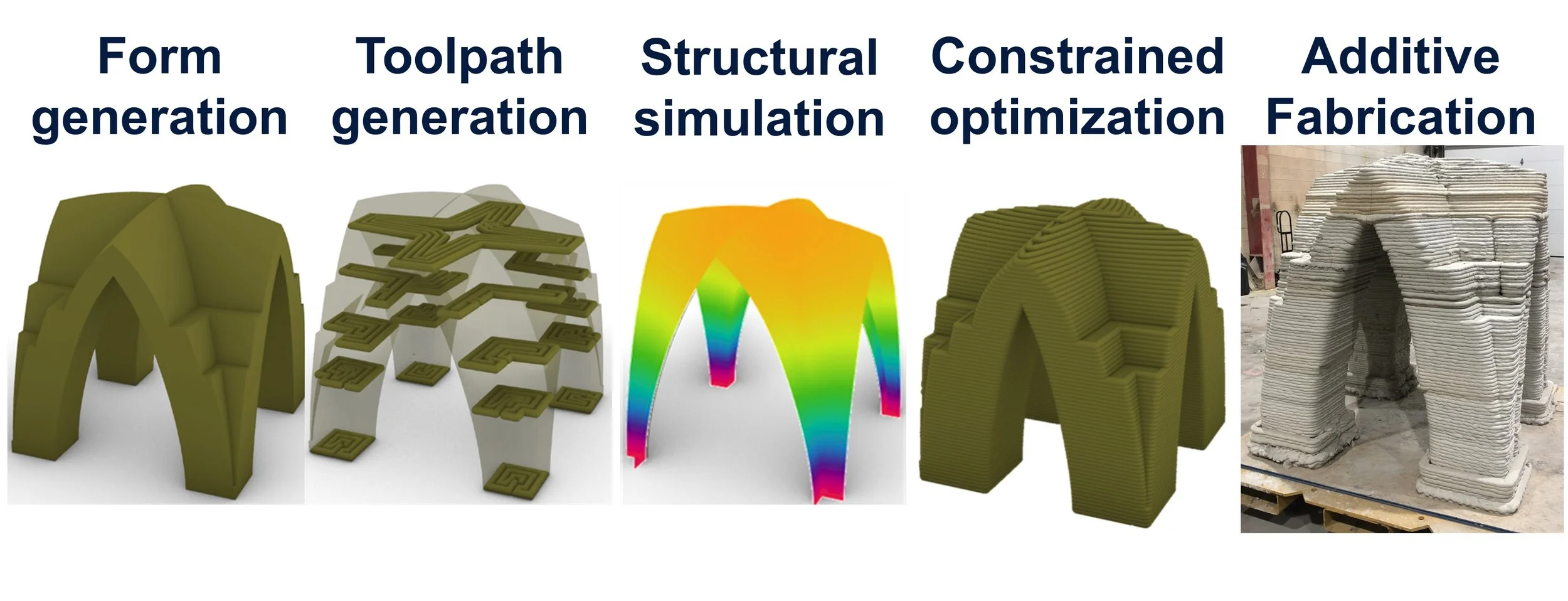
This workflow supports the design of vaults for 3DCP. By optimizing the structural form while considering factors such as toolpath design, buildability, and the fabrication process, it is possible to efficiently design and fabricate vault structures.
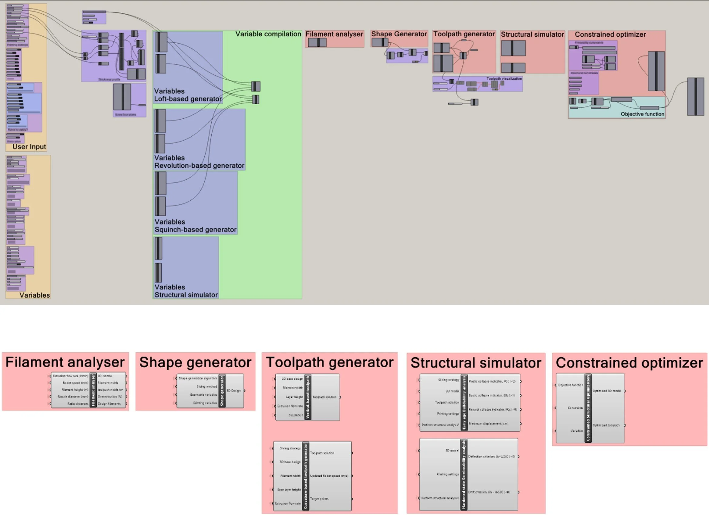
The proposed design optimization workflow consists of six components developed in Grasshopper, each corresponding to a step in the workflow: (1) filament shape predictor; (2) form generator; (3) toolpath generator; (4) structural simulator; (5) performance-based constrained optimizer; and (6) Rapid code generator.
Author:
Gonçalo Marques Duarte
Committee members:
Jose Pinto Duarte, Ph.D.
Nathan Brown, Ph.D.
Part 2 - Form generator of vaults for 3DCP
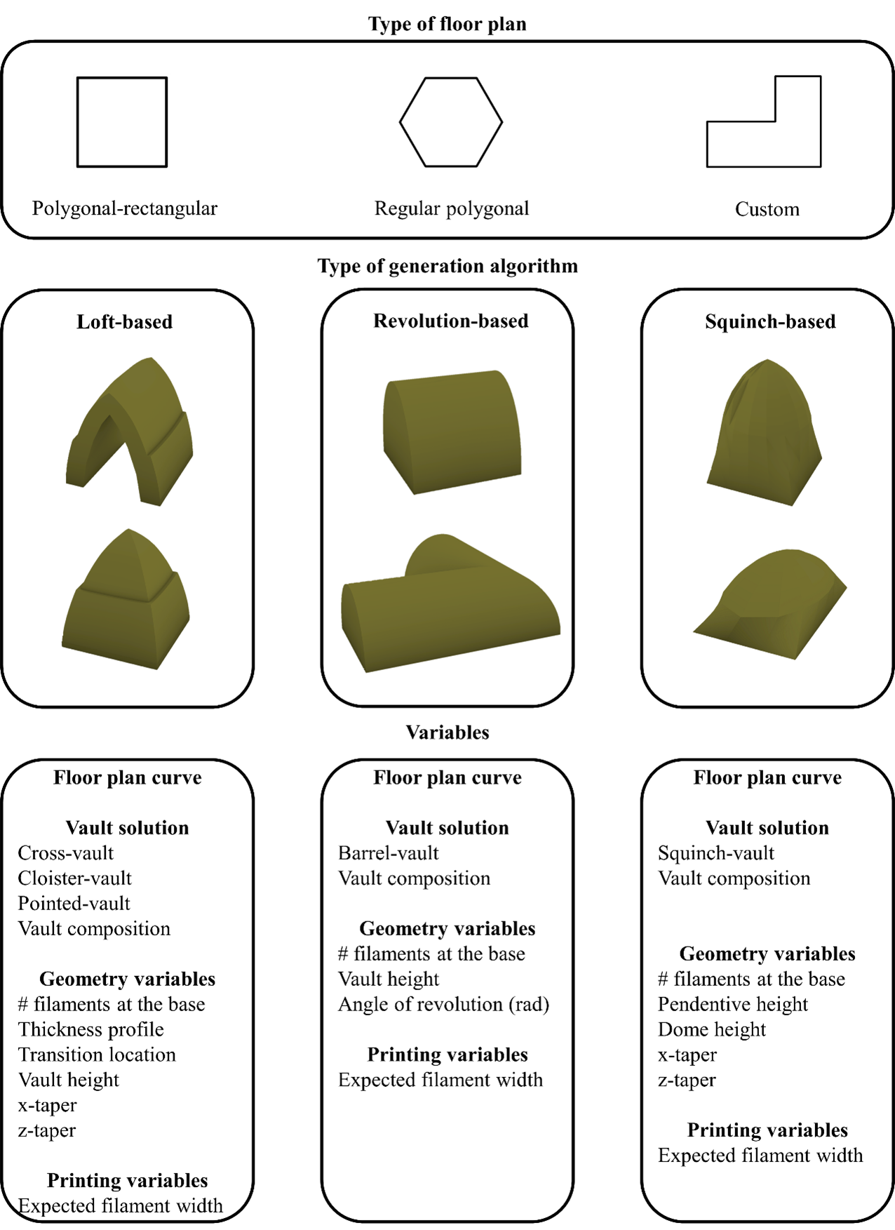
The second step of the workflow involves the form generator, which considers the straight or curved line representing the limits of a room to dynamically produce an enclosure. To accomplish this, it employs one of three different parametric models. The first considers an algorithm that uses loft operations and specifically caters to regular polygonal floor plans. The second involves an algorithm that generates vault surfaces using revolution operations and applies to rectangular floorplans. The third employs an algorithm that creates squinch-vault structures. Squinches are surfaces that transition between angular and curved surfaces and the algorithm permits to cover a polygonal room with a dome that is circular at the top. Besides the input line, the generator uses a set of geometric variables that is contingent upon the selected algorithm.
Part 1 - Filament generator
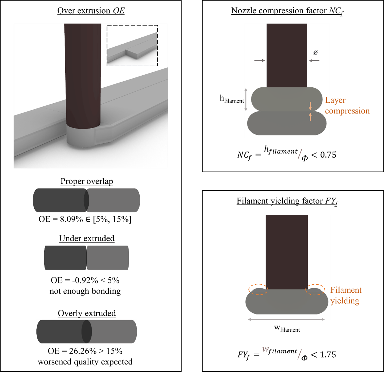
Filament shape prediction precedes path generation because it is necessary to establish the path width wtoolpath and predict the quality of the printed filament. Variables related to printing settings such as robot speed sr, extrusion flow rate Q, filament height hfilament, filament width wfilament, nozzle cross-sectional area Anozzle, nozzle diameter , and adjacent filament overlap are input to generate the geometry of the filament. Filament design depends on the printing process and should be oriented towards assuring adequate structural performance and printing quality.
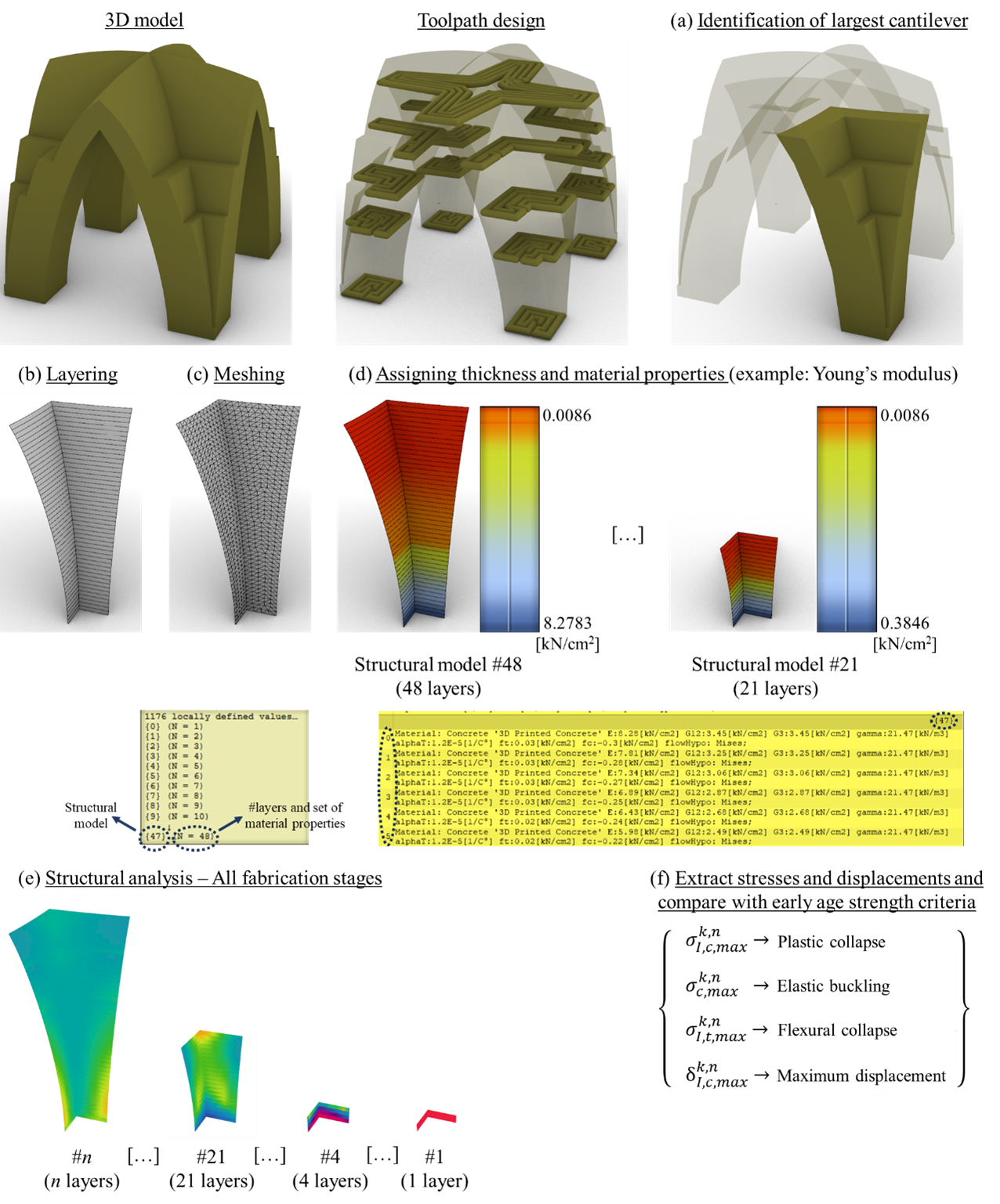
Part 4 - Structural simulator
The simulation starts by slicing the shell structure into layers, each matching the toolpath height. Material properties are assigned based on cumulative printing time, calculated from the toolpath length. Each layer is modeled using triangular shell elements with a height equal to the layer thickness. The analysis focuses on early-age buildability, assessing stability as each new layer is added. For an element with n layers, n structural analyses are performed, each reflecting the material’s evolving properties over time.
A. Horizontal slicer
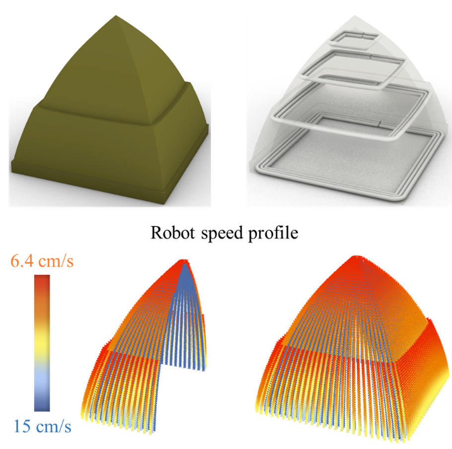
For curvature-based slicing, also known as radial vaulting, the model is divided into concentric shells spaced by the filament width. The innermost shell is then sliced by radial planes spaced by the layer height, producing inner isocurves. These curves are divided into points and projected onto the outer shells along normal vectors, forming curvature-based isocurves connected by polylines. Each layer is then linked using a method similar to horizontal slicing. Because the outer filaments cover a larger distance due to curvature, the robot automatically slows down on these regions to ensure consistent extrusion.
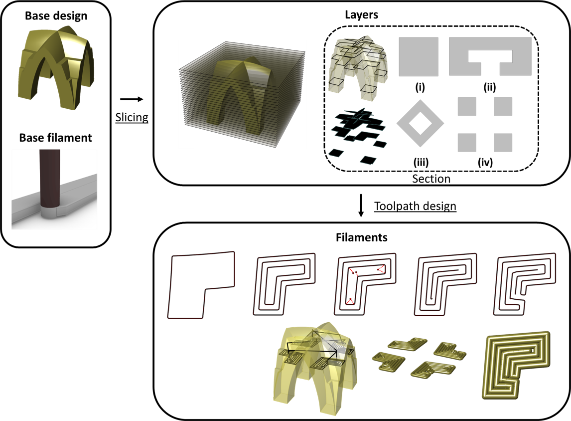
Part 3 - Toolpath generator/Slicer
The toolpath generator operates based on multiple inputs, namely the vault design, fabrication parameters (including toolpath width, filament height, robot speed, and extrusion flow rate), chosen slicing strategy (horizontal or curvature-based), and the fabrication sequence. The algorithm of the toolpath generator was conceived to completely fill each layer. This algorithm foresees two slicing strategies, namely horizontal slicing and curved slicing.
For horizontal slicing, or corbeling, the vault is divided into evenly spaced layers based on the layer height. Each layer is classified by surface type and subdivided into isocurves generated by offsetting boundary curves by half a filament width. For hollow surfaces, the inner boundary guides the offsets. The resulting paths are connected with small gaps at seams and linked across sections with travel moves. Toolpaths are printed from the inside out to ensure clean boundaries and prevent material overlap.
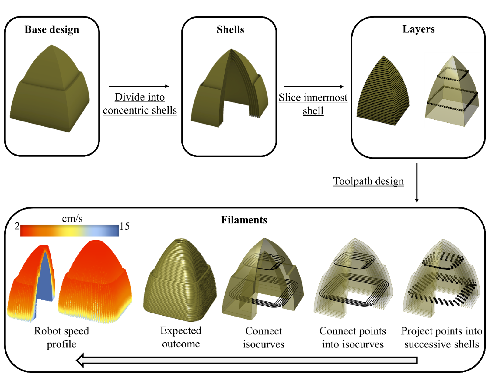
B. Curvature-based slicer
Part 5 - Constrained Optimizer
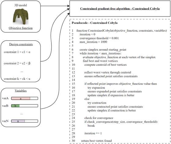
This step proposes constrained, gradient-free, single-objective optimization to optimize structures for 3DCP. The reason is twofold. First, gradient-free methods are suitable for 3DCP because of the difficulty in computing derivatives of objective functions, such as toolpath length, that depend on geometry and printing settings and therefore cannot be expressed as a continuous function. Second, the use of constraints helps filter the design space to find a solution that both minimizes the objective function and meets design requirements.
Part 6 - Robotic code generator
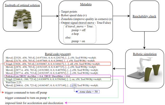
The rapid code generator takes a toolpath solution and determines the target points, robotic axis movements, and assigns a robot speed and output control signal to each target point. In this context, the output control signal consists of a Boolean True/False value assigned to each target point. If the signal is True, then there is a travel move and the pump turns off.
Furthermore, the rapid code generator performs the robotic arm reachability check to verify that all target points fall within the operational reach of the robotic arm.
Design optimization of a vault
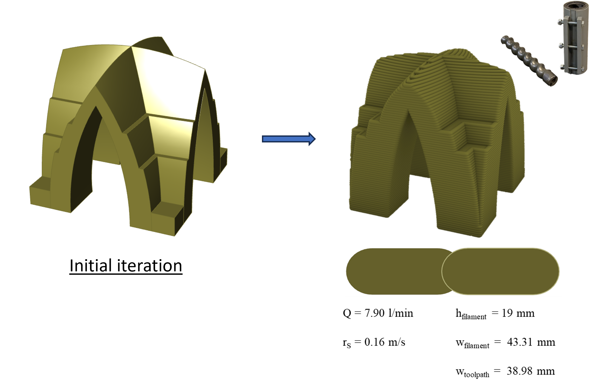
The workflow was applied to the design of a cross-vault structure that encloses a 4ft x 4ft room. The resulting printing setting consisted of an extrusion flow rate (Q) equal to 7.90l/min, and a robot speed (rs) equal to 0.16 m/s.
Applying the workflow to several types of vault solutions
The workflow was tested in other forms besides the cross-vault. Both squinch- and cloister- vaults showcased lower material consumption, overhangs and stresses compared to the cross-vault.
